

Last Updated: November 13, 2026
Quick Summary
To monitor redundant power systems, watch each power path separately from the UPS outward: track input voltage, output load, battery state and transfer events on every UPS, add per-branch PDU monitoring, and feed it all into SNMP polling plus traps. Alert on lost redundancy, not just total failure, and test each path on a schedule.
- Poll every 60 seconds for trends and use traps for immediate event notification, never traps alone.
- Alert when one path fails and redundancy is lost, not only when both paths are gone.
- Require two consecutive bad polls before alerting to prevent single-poll spikes creating noise.
- Escalate a warning that stays open for four hours to critical by time, not just severity.
- A test passes only if load held, the correct alert fired and reached on-call, and the record shows recovery.
Table of Contents
- What Redundant Power Systems Need From Monitoring
- Start With UPS Monitoring at the Source
- Extend Visibility With PDU Monitoring
- Build the Alert Layer With SNMP Power Monitoring
- Design Power Supply Failure Alerts That Get Acted On
- Test Redundancy Without Taking the Load Down
- Plan Your Monitoring Rollout With Treske
- Frequently Asked Questions
What Redundant Power Systems Need From Monitoring
Redundant power systems are arrangements of two or more power paths that keep equipment running when one path fails. Monitoring those systems means watching each path separately, so a hidden failure never leaves you with a single point of failure. This guide covers how to monitor redundant power systems step by step, from the UPS outward to your alerting layer.
Redundancy only works while every path is healthy. The moment one side fails silently, you are running on a single supply and nobody knows. Monitoring closes that gap.
The Failure Modes Monitoring Must Catch
A redundant supply fails in quiet ways. The load keeps running, so nothing looks wrong.
- One path dead, load unaware: a PSU or UPS module drops out and the other carries everything.
- Shared upstream fault: both paths draw from one circuit or one distribution board.
- Battery decline: the UPS runs but its runtime is shrinking.
- Silent comms loss: the management card stops reporting, so you see stale data.
- Nuisance tripping: a rack power strip trips and takes a path offline.
For tripping symptoms and their causes, see our guide to server rack power strip tripping.
Start With UPS Monitoring at the Source
UPS monitoring is the foundation of any redundant power setup. It reports input power, output load, battery state and transfer events from the unit itself. Start here because the UPS sees every upstream disturbance first.
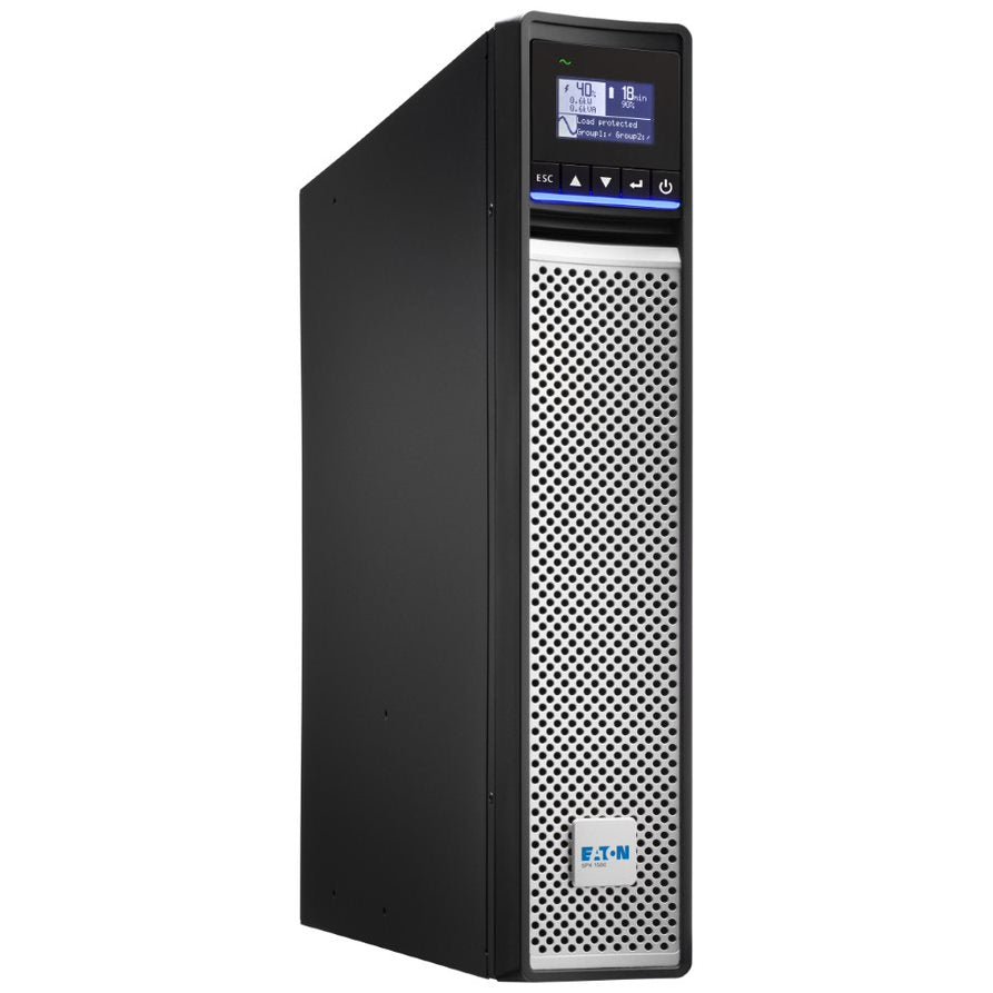
Watch these values on each UPS:
- Input voltage and frequency
- Output load as a percentage of capacity
- Battery charge and estimated runtime
- Transfer and bypass events
- Temperature inside the unit
Log them continuously. A single reading tells you little; a trend shows battery decline weeks before it bites.
Reading Status Indicators and DC-OK Relay Contacts
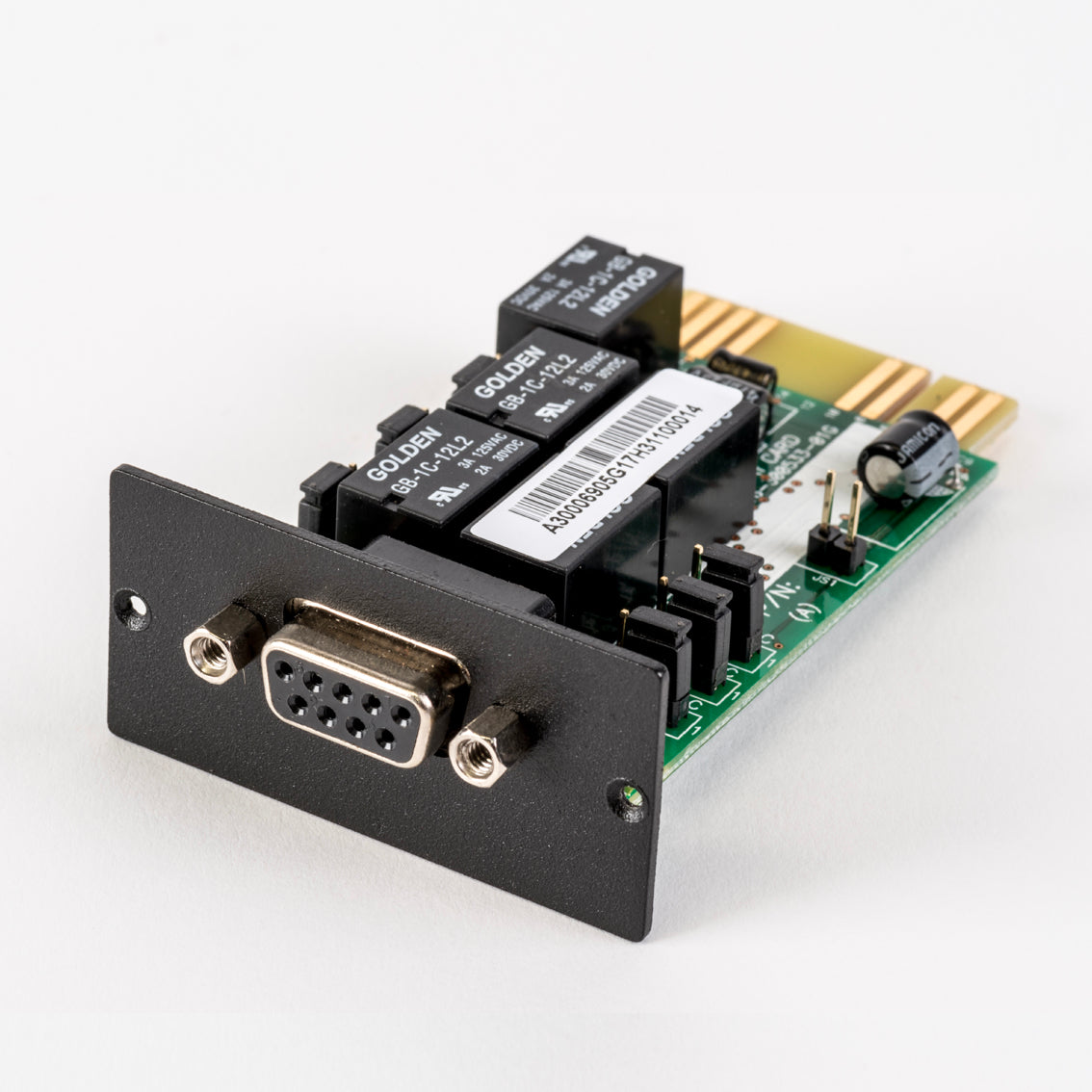
Status indicators and relay contacts give you a hard-wired signal that needs no network. A DC-OK relay contact is a dry contact that changes state when the power supply output is healthy. Wire it into your monitoring or alarm panel and you get a positive signal even if the network is down.
Read the LED indicators first, then confirm with the relay. Many supplies also offer a status output you can wire into a relay comms card, such as the PowerShield internal relay comms card with DB 9 connector.
Extend Visibility With PDU Monitoring
PDU monitoring adds the layer between the UPS and the rack. A power distribution unit reports per-outlet current, voltage and load, so you can see which circuit is stressed.
Check per-branch current against breaker ratings. Compare phase loads where you run three-phase distribution. Watch for voltage drop under load, which points to cabling or connection problems.
Set a baseline in the first week, then alert on deviation rather than absolute values. A branch that creeps upward over a month is telling you something.
Build the Alert Layer With SNMP Power Monitoring
SNMP power monitoring turns device data into alerts your team can act on. Simple Network Management Protocol lets your UPS, PDU and environmental devices report to one management platform.
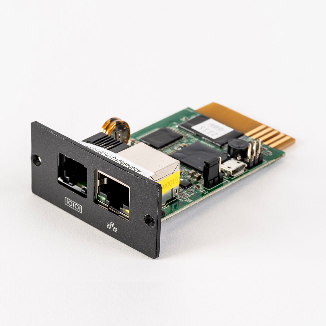
Install an SNMP card in each UPS and point it at your network management system. Cards such as the PowerShield internal SNMP network card provide remote monitoring and scheduled shutdown control for compatible UPS systems, and other providers offer similar management cards with browser and command-line access.
Poll, Trap, or Both
Use both, but for different jobs. Polling on a fixed interval (60 seconds is a common starting point) gives you trend data and catches silent failures where a trap never fires. Traps give you immediate event notification, but they are UDP and can be lost, so never rely on traps alone.
- Poll for input voltage, output load, battery capacity, runtime remaining, temperature and device uptime.
- Trap for power-loss, transfer-to-battery, low-battery, overload, fan-fail and comms-loss events.
- Heartbeat with a sysObjectID or uptime poll so a dead card is visible as missing data, not as a quiet dashboard.
OIDs and MIBs That Matter
Load the vendor MIB into your management platform before you build alerts. The standard UPS MIB (RFC 1628) exposes values such as battery status, estimated minutes remaining, output load percentage and input voltage; vendor MIBs add PSU-specific status, per-outlet current and environmental sensors. Map at least these to your platform:
- Battery status and estimated runtime remaining
- Output load as a percentage of capacity
- Input voltage and frequency
- PSU or module status where the device exposes it
- Temperature and humidity from environmental probes
If a value has no OID, it cannot be alerted on. Check the MIB walk before you promise a monitoring outcome.
Thresholds and Alert Design
Set thresholds from your own baseline, not from defaults. A load alert at 80% of capacity suits many racks; pick your own number and document why.
Use three tiers and route them differently:
| Tier | Example event | Response |
|---|---|---|
| Critical | Both paths lost, load on battery | Call out, immediate |
| Warning | One path failed, redundancy lost | Investigate same day |
| Info | Transfer event, path restored | Log and review weekly |
Escalate by time, not just by severity. A warning that stays open for four hours becomes critical.
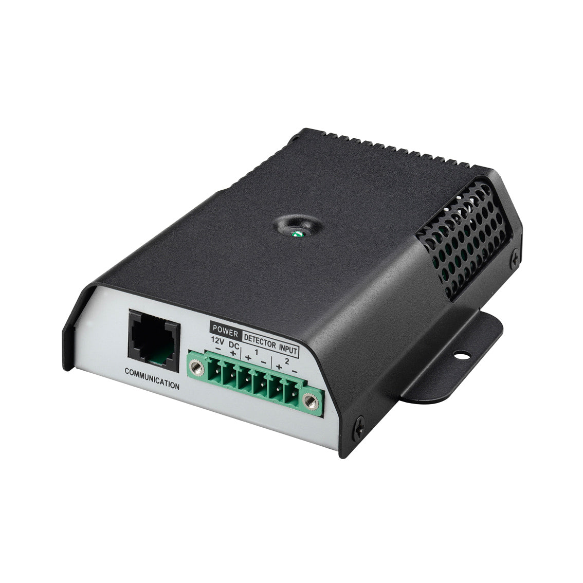
An environmental monitoring device that feeds the same SNMP platform, such as the PowerShield environmental monitoring device, keeps temperature and humidity alerts in one place.
Watch out: a management card that loses network connectivity looks identical to a healthy device if you only alert on traps.
Design Power Supply Failure Alerts That Get Acted On
Power supply failure alerts fail when they are too noisy or too quiet. Design them around severity, ownership and escalation, not around every possible event. An alert nobody acts on is worse than no alert.
Use three tiers:
| Tier | Example event | Response |
|---|---|---|
| Critical | Both paths lost, load on battery | Call out, immediate |
| Warning | One path failed, redundancy lost | Investigate same day |
| Info | Transfer event, path restored | Log and review weekly |
An environmental monitoring device that feeds the same SNMP platform, such as the PowerShield environmental monitoring device, keeps temperature and humidity alerts in one place.
Thresholds, Escalation and False Alarm Control
Set thresholds from your own baseline, not from defaults. A load alert at 80% of capacity suits most racks; pick your own number and document why.
Escalate by time, not just by severity. A warning that stays open for four hours becomes critical.
Control false alarms by requiring two consecutive bad polls before alerting. Single-poll spikes create noise and train people to ignore alerts.
Test Redundancy Without Taking the Load Down
Testing proves the monitoring actually works. Simulate a failure on one path and confirm the alert fires, the load holds and the record is accurate. Do this on a schedule, not once at handover. The gap most guides leave is the procedure: what to check before you pull anything, what a pass looks like, and how to get back safely.
Before You Touch Anything
- Confirm the remaining path can carry full load with headroom. If the second path is already near capacity, do not test under load.
- Confirm the UPS battery is charged and runtime is sufficient for the test window.
- Confirm you have a written rollback step and a second person watching the load.
- Confirm alerts are routed to a channel someone is actually watching during the test.
- Schedule the test outside change-freeze periods and tell the affected team.
Follow a commissioning process that covers safe redundancy testing before go-live, as set out in our guide to the data centre power commissioning process. Then repeat the key checks each year.
A Safe Failure-Simulation Sequence
- Baseline the load. Record per-path current, output load percentage and runtime before you change anything.
- Pull one input feed at the source, not at the rack, and confirm transfer. Watch the load stay up and the alert fire within your expected window.
- Disable one PSU in a dual-supply server and watch the load shift to the remaining supply. Confirm the server reports the lost supply and the monitoring platform records it.
- Silence the network card (disable the port or block SNMP) and confirm a comms-loss or missing-heartbeat alert fires.
- Trip a PDU branch and check the alert path end to end, including escalation if it is not acknowledged.
- Verify the DC-OK contact changes state at the alarm panel, not just on the device LED.
- Restore each path and confirm the alert clears and the record shows recovery.
Pass and Fail Criteria
A test passes only if all of these are true: the load held without interruption, the correct alert fired within the expected time, the alert reached the on-call person, and the record shows both the failure and the recovery. If any one fails, fix the monitoring before the next test, not after the next outage.
Watch out: testing without a written rollback step is how a routine check becomes an outage. Confirm the remaining path can carry full load before you pull anything, and restore the path you changed before starting the next step.
Plan Your Monitoring Rollout With Treske
A monitoring rollout works best in stages: UPS first, then PDU, then alerting, then testing.
Start with one room, prove the alerts, then scale. Get started with Treske and build a monitoring layer that catches the failure before the load does.
The real test of redundancy is not whether it works on day one, but whether you would know if it stopped. Build the monitoring layer before you need it, and test it while the load is safe.
Frequently Asked Questions
How can you tell if a redundant power supply has failed?
Check the status indicators on each power supply unit first: a healthy PSU shows a solid green LED, while a failed or degraded unit typically shows amber, red or no light. Next, confirm in your management interface or SNMP power monitoring platform whether the unit has dropped off the network or logged an input power loss event. A DC-OK relay contact wired to a dry-contact input also gives a hard signal. Because a redundant system keeps running on the surviving supply, the failure is silent unless you are actively watching these signals.
How do you set up alerts for power supply failures?
Decide what matters most: loss of input power, PSU fault, battery on UPS, and load above threshold. Configure these as traps or polling checks in your SNMP power monitoring tool, then route them to a channel someone actually watches, such as an on-call phone or a ticketing queue. Set a short repeat interval for critical alarms and suppress duplicates. Test each alert by simulating the condition during a planned window so you know the notification path works before a real event.
Should redundant power supplies be connected to separate circuits?
Yes. Two power supplies fed from the same circuit, PDU or upstream switch give you almost no protection, because one trip takes both down. Each PSU should be fed from a separate power distribution path, ideally separate circuits on separate distribution boards, and in a 2N design, separate UPS systems. This is the difference between redundancy on paper and redundancy in practice, and it is the most common design fault found during site acceptance testing.
How often should redundant power systems be tested?
Run a monitoring and alerting check monthly, a transfer or failover test quarterly, and a full functional test of the redundancy path annually, plus after any change to the power distribution. Battery strings on UPS units need their own schedule, usually an impedance or capacity check each year. Record every test result so you can show a trend. Testing matters because a redundant system that has never been exercised often fails at the moment it is needed.
