


Table of Contents
- Why Rack Enclosure Airflow Management Decides Your Cooling Bill
- Step 1: Map Airflow Paths and Find Bypass Airflow Leaks
- Step 2: Best Practices for Blanking Panels and Segregation Panels
- Step 3: Cable Management That Stops Airflow Obstruction
- Step 4: Containment Systems for Hot Aisle and Cold Aisle Segregation
- Is Modular Cooling Good for Small Server Rooms?
- Server Rack Thermal Management Tools for Monitoring and Validation
- Maintenance Schedules and Common Mistakes to Avoid
- Frequently Asked Questions
Last Updated: September 16, 2026
Why Rack Enclosure Airflow Management Decides Your Cooling Bill
Optimizing rack enclosure airflow management means controlling how cold air reaches server intakes and how hot exhaust leaves the rack, so cooling systems work with the equipment instead of against it. At Treske Pty Limited, we see the same pattern across critical facilities: cooling capacity gets added to solve a problem that better airflow discipline would have fixed for a fraction of the cost.
Step 1: Map Airflow Paths and Find Bypass Airflow Leaks
Start by tracing where air actually goes, not where the floor plan says it should. Bypass airflow is cold air that escapes through gaps, open rack units, or cable cutouts without ever cooling a server, the largest hidden waste in most server rooms.
Walk the room and check:
- Open U positions in every rack
- Missing or loose blanking panels
- Cable entry points in the rack roof and floor
- Gaps between rack frames and adjacent racks
- Under-floor tile cutouts larger than the cables passing through them
Checking Intake Air, Exhaust Air and Static Pressure
Measure intake air temperature at the front of each rack and exhaust air temperature at the rear. A wide gap confirms the rack is doing its job; a narrow gap usually means recirculation, where hot exhaust curls back into the cold aisle. Static pressure differences between the cold and hot aisle tell you whether air is delivered where it is needed.
Step 2: Best Practices for Blanking Panels and Segregation Panels
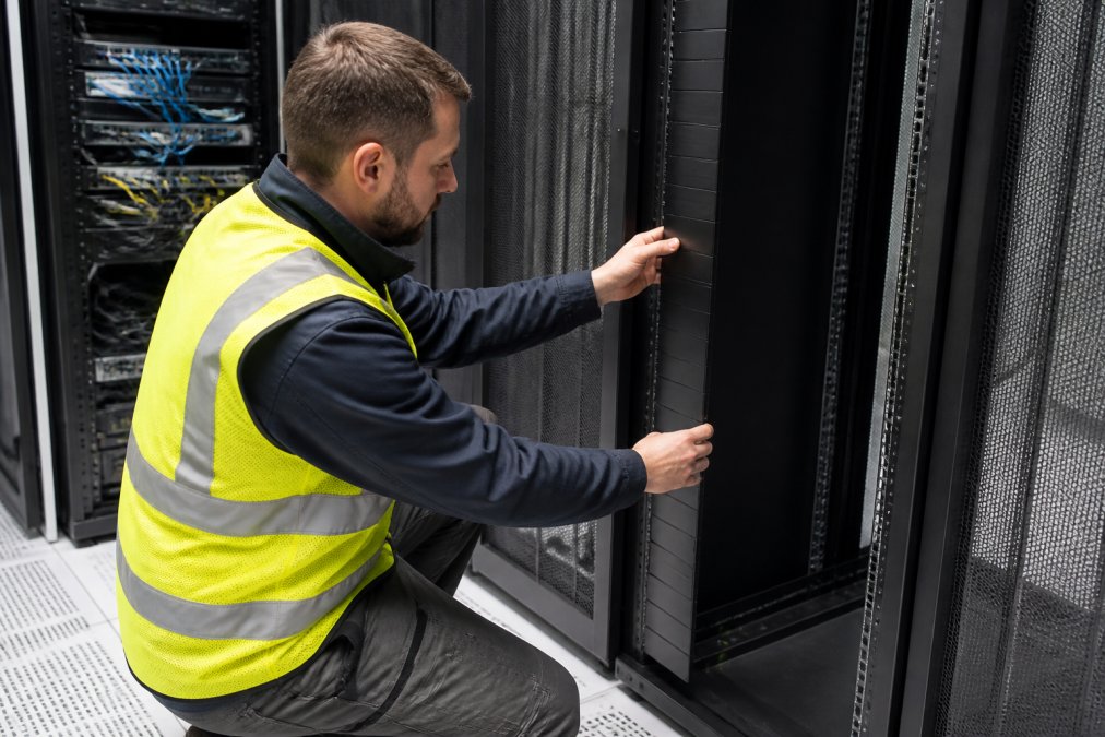
Blanking panels are the cheapest fix with the fastest payback. Every empty U should be covered, because an open slot lets cold air escape into the hot aisle without doing any work.
Step 3: Cable Management That Stops Airflow Obstruction
Cable management is airflow management. Cables routed through the front of a rack block intake air as effectively as a closed door, and rear cable sprawl traps exhaust heat against the equipment.
Vertical PDU Placement and Rear Cable Routing
Vertical PDUs belong at the rear or side of the rack, never across the exhaust path. Mounting one in the rear centre forces hot air around it, raising exhaust temperatures and fan speeds. Route rear cables downward and outward, keeping a clear vertical channel for exhaust air to rise and leave the rack.
Step 4: Containment Systems for Hot Aisle and Cold Aisle Segregation
Containment systems physically separate hot aisle and cold aisle air so the two never mix. Cold aisle containment encloses the intake side; hot aisle containment encloses the exhaust side and directs hot air back to the cooling unit.

Is Modular Cooling Good for Small Server Rooms?
Modular cooling is often the better choice for small server rooms, but the decision should be driven by rack power density rather than room size alone. A small room with two or three racks rarely justifies a large fixed CRAC unit running at partial load, which wastes energy and delivers uneven airflow. Modular options scale with actual thermal load instead of a capacity you may never reach.
Matching the Cooling Approach to Rack Density
Cooling approach |
Typical rack density |
Best for |
Key trade-off |
|---|---|---|---|
Room-level CRAC with containment |
Up to ~5 kW per rack |
Large, open halls with low density |
Long air paths, higher losses |
Rack-mounted airflow unit |
1-3 kW per rack |
Single racks, edge sites |
Limited capacity per unit |
In-row cooling |
5-15 kW per rack |
Small to mid server rooms |
Needs free rack space in the row |
Rear-door heat exchanger |
10-25 kW per rack |
Retrofits where floor space is fixed |
Adds depth to the rack, needs water or refrigerant |
Direct-to-chip liquid cooling |
25 kW+ per rack |
High-density compute, AI workloads |
Significant infrastructure change |
In-row and rack-mounted options fit the lower-density end of that spectrum well. The APC InRow Airflow Cooling System is a 30 kW in-row unit that sits within the row itself, drawing hot exhaust directly and returning cold air close to the intake. That shortens the air path considerably compared with a perimeter unit pushing air across the room.
Why Airflow Discipline Matters More as Density Rises
As rack density climbs, the margin for error shrinks. At 2 kW per rack, a missing blanking panel is an annoyance. At 12 kW per rack, the same gap can push intake temperatures past the point where servers throttle, because there is less cold air to spare. Airflow optimisation and cooling technology selection are not separate projects, they are the same project viewed from two angles.
Retrofitting Modular Cooling Into an Existing Room
Modular cooling is particularly attractive in retrofits, because it can be added rack by rack without shutting down the room. The constraint is usually physical: in-row units need free U space and a path for condensate or refrigerant lines, and rear-door heat exchangers need rear clearance for service access. Plan those routes before committing to a unit, because retrofitting pipework around live racks is where most of the cost and disruption sits.
Server Rack Thermal Management Tools for Monitoring and Validation
Server rack thermal management tools turn airflow work from a one-off project into something you can verify. Without measurement, you are guessing, and guessing is how cooling bills creep back up. Most guides stop at installation advice; the step that protects your investment is validation, proving the airflow changes did what you intended, and catching drift before it becomes a hot spot.
What to Measure at the Rack
At minimum, deploy rack-level temperature sensors at both intake and exhaust, plus room-level environmental monitoring. The metrics that matter most are:
- Intake air temperature at the front of each rack. This governs equipment reliability. A common target is the range recommended by the server manufacturer, typically around 18-27°C for most enterprise equipment, though always check the specific equipment datasheet.
- Delta T between intake and exhaust. A healthy rack shows a clear temperature rise across the equipment. A narrow delta usually signals recirculation or bypass, where cold air is not doing useful work.
- Static pressure differential between cold and hot aisle. This tells you whether air is being delivered where it is needed, and whether containment is holding the separation.
- Humidity. Too low risks electrostatic discharge; too high risks condensation. Room-level monitoring usually covers this.
Using CFD and Thermal Mapping to Validate Design
Where budget allows, CFD (Computational Fluid Dynamics) modelling maps airflow patterns before you spend on hardware, and again after installation to confirm the result. For most facilities, a lighter-weight approach works well: a handheld thermal camera or a grid of portable sensors used to build a thermal map of the room. Walk the cold and hot aisles and look for temperature gradients that suggest air is short-circuiting or pooling.
A simple validation routine after any airflow change:
- Record baseline intake and exhaust temperatures at every rack before the change.
- Make one change at a time, for example, fit blanking panels across a single rack.
- Wait for the room to stabilise, typically 30-60 minutes depending on the cooling system.
- Re-measure and compare. If intake temperature did not improve, investigate before moving to the next change.
- Log the result so the next person can see what worked.
Feeding Results Into Efficiency Reporting
Thermal monitoring at the rack level also feeds into PUE (Power Usage Effectiveness) calculations, giving you a defensible number for efficiency reporting. PUE is total facility power divided by IT equipment power; a lower number means more of your electricity does useful compute work rather than cooling. Airflow optimisation typically shows up as a PUE improvement because cooling units can run at higher return air temperatures and lower fan speeds.
Retrofitting vs New Builds: What Changes
Retrofitting changes the sequence, not the principles. In a new build you can design containment, cable routing and PDU placement from the start, and specify monitoring as part of the fit-out. In a retrofit, you inherit existing cable runs, floor tile layouts and rack positions, so the work becomes staged: seal the easy wins first, then plan containment around what is already installed, and add monitoring where it can be retrofitted without downtime.
A Quarterly Maintenance Cadence
Airflow gains decay. Panels get removed and not replaced, cables get added in a hurry, and containment doors get propped open during maintenance. A quarterly walkthrough that checks panels, cable routing, containment seals and sensor readings keeps performance where you set it. Between walkthroughs, rely on your monitoring alerts to flag anything that changes suddenly.
Common mistakes we see:
- Fitting blanking panels only at the rear of the rack
- Running cables across intake faces during emergency changes
- Mounting vertical PDUs in the rear centre of the rack
- Leaving containment doors open after maintenance
- Adding cooling capacity before checking bypass airflow
- Treating monitoring as a one-off installation rather than an ongoing discipline
Maintenance Schedules and Common Mistakes to Avoid
Common mistakes we see:
- Fitting blanking panels only at the rear of the rack
- Running cables across intake faces during emergency changes
- Mounting vertical PDUs in the rear centre of the rack
- Leaving containment doors open after maintenance
- Adding cooling capacity before checking bypass airflow
If your team would rather not carry this alone, Treske Pty Limited provides preventative maintenance and site acceptance testing so airflow performance is measured against design, not assumed.
Frequently Asked Questions
Why is rack airflow management important for data centre cooling?
Poor rack enclosure airflow forces cooling units to work harder to remove the same thermal load. When hot exhaust air recirculates back into equipment intake air, supply temperatures rise and hot spots form. Correcting bypass airflow, sealing gaps and containing aisles lowers return air temperatures, which lets chillers run less often. That directly reduces energy savings and protects equipment lifespan, particularly in high-density rows where a single unsealed U position can shift the whole rack's thermal profile.
What are the best practices for blanking panel installation?
Fill every unused U position in the front of the rack, not just the obvious gaps. Use tool-less snap-in panels sized to the exact U height rather than stacking smaller panels, which leaves hairline gaps. Install them at the front of the rail so cold air cannot escape into the hot aisle, and check that panels sit flush against the rail without bowing. Recheck after every hardware change, since decommissioned equipment is the most common source of new bypass airflow.
How do cable management solutions impact server rack airflow?
Cables routed loosely across the rear of a rack block exhaust air and create turbulence that raises static pressure. Using vertical cable managers, structured rear pathways and correctly sized patch leads keeps the exhaust path clear. Vertical PDUs mounted at the rear side rails also free up space that would otherwise be filled with power leads crossing the airflow path. The result is lower static pressure across the rack, which means fans run at lower speeds and draw less power.
How can I identify thermal hotspots in my server rack?
Start with a thermal monitoring tool that logs intake air temperature at multiple heights in each rack, not a single sensor at the top. Compare readings across the front and rear of the enclosure, then use CFD modeling or a handheld thermal camera during peak load to confirm where recirculation is occurring. Persistent differences of more than a few degrees between the bottom and top of a rack usually point to bypass airflow or containment gaps that need sealing.