

Last Updated: November 5, 2026
Quick Summary
Zero downtime cutovers are planned infrastructure or system switches where the production environment keeps serving users throughout, with no measurable break in service availability. Delivering them requires two working paths for everything, a tested failover plan, a rehearsed rollback route, and a cutover window that takes minutes rather than hours.
- Core data centres averaged 2.4 total facility-wide downtime events in a year, per Vertiv and Ponemon Institute's 2025 report.
- An ATS only helps if the two feeds are genuinely independent, not from the same upstream board.
- Test failovers in order and record the actual gap for each event, not the theoretical one.
- Most dual-run migration periods exceed initial project estimates by 24 months, per LegacyLeap's 2026 research.
- Keep the old path live and monitor error rates and latency for a full business cycle before decommissioning.
Table of Contents
- What Zero Downtime Cutovers Actually Require
- Redundant Power Supply Systems for Data Centres
- Load Balancer Redundancy and Traffic Routing
- Failover Testing Procedures Before the Cutover Window
- Parallel Run, Staged Migration and Gray Cutover
- Database Synchronisation, Integrity Validation and Rollback
- Your Zero Downtime Migration Checklist
- Planning Your Cutover with Treske
- Frequently Asked Questions
What Zero Downtime Cutovers Actually Require
Zero downtime cutovers are planned infrastructure or system switches where the production environment keeps serving users throughout, with no measurable break in service availability.
The scale of the problem is well documented. According to Vertiv and Ponemon Institute's 2025 Data Center Downtime at the Core and the Edge report, core data centres experienced an average of 2.4 total facility-wide downtime events in a year.
Power, cooling and rack systems are central to making these cutovers possible. Here is what it takes:
- Two working paths for everything. No single point of failure in power, network or data flow.
- A tested failover plan. Redundancy you have never switched is just a hope.
- A rollback route. The ability to return to the old state fast if the cutover goes wrong.
Below, we break down each layer, from the power feed to the database, and show how to plan a cutover you can trust.
Redundant Power Supply Systems for Data Centres
Redundant power supply systems for data centres are the foundation of any zero downtime cutover.
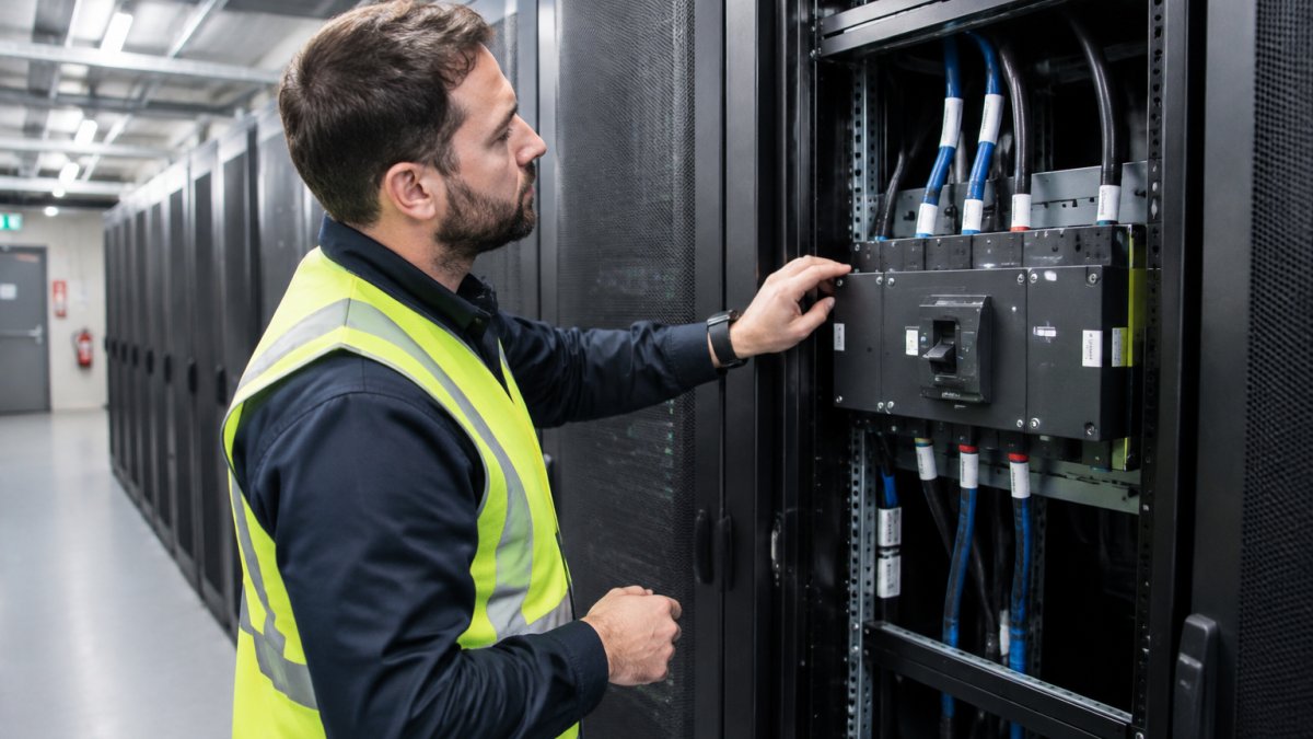
The core principle is the A/B feed model. Two independent power sources feed the rack, and each device draws from both.
If you are weighing whether an N+1 design justifies the spend, our review of whether N+1 power architecture is worth it breaks down the trade-offs.
Automatic Transfer Switches and the A/B Feed Model
An automatic transfer switch makes the A/B feed model work.
For single-corded devices, this is essential. Rack-mount units like the Vertiv load transfer switch or the CyberPower switched ATS sit in a 1U slot and handle the switch automatically.


Watch out: an ATS only helps if the two feeds are genuinely independent. Two feeds from the same upstream board share a single point of failure.
Load Balancer Redundancy and Traffic Routing
Load balancer redundancy keeps traffic flowing when a node or a data centre path drops.
The balancer itself must not be a single point of failure. Run them in pairs, with health checks that pull a failed node out of rotation in seconds.
For systems built on parallel UPS modules, the hardware side needs its own redundancy. Parallel modules like the Eaton System Parallel Modules let you build modular UPS capacity where one module can drop out without taking the system down.
Traffic routing and latency go together. A cutover that adds 200ms of latency to every request is not zero downtime in the eyes of your users.
Failover Testing Procedures Before the Cutover Window
Failover testing procedures are the rehearsals that prove your redundancy works before you rely on it. A failover plan that has never been tested is a guess. This section covers what to test, how to automate it, and what should never be automated.
Test in this order, and record the actual gap for each event rather than the theoretical one:
- Pull one power feed. Confirm the ATS switches and the load holds.
- Take a UPS module offline. Confirm N+1 capacity covers it.
- Kill a load balancer node. Confirm traffic reroutes without errors.
- Simulate a database failover. Confirm the standby takes over cleanly.
- Time each event. The measured gap is the number that goes in the cutover plan.
Run these tests during low-traffic periods, and log every result. If a test fails, fix it before the real cutover, not during it.
Turning failover tests into automated gates
The difference between a rehearsal and a gate is automation. A rehearsal is a person running steps and writing down what happened. A gate is a pipeline stage that fails the cutover if the result is outside tolerance.
A workable pattern is to script each failover test as a repeatable job in your CI/CD pipeline, with a pass/fail assertion attached:
- Power path test, trigger the ATS, assert the load held and the transfer completed within the expected time.
- Load balancer test, drain a node, assert error rate stayed within tolerance and requests rerouted.
- Database failover test, promote the standby, assert replication lag closed and the application write path recovered.
Each job should emit a machine-readable result, and the cutover should be blocked unless every gate is green. That converts "we tested it once" into "it is tested every time the pipeline runs", the only version that survives staff turnover.
Automated versus manual cutover workflows
Automated cutover workflows run the switch through scripts and orchestration tools. Manual workflows rely on an engineer running a checklist.
Automation wins on speed and repeatability.
Manual steps suit the parts that need judgement: confirming data integrity, deciding whether to roll back, signing off the window.
Eaton ATS w/Serial Port - (2)C20 16A Input, (8)C13, (1)C19 Outlets →
A useful decision rule: automate anything that is deterministic, reversible and time-sensitive; keep manual anything that requires a judgement call about business risk.
Parallel Run, Staged Migration and Gray Cutover
A parallel run keeps the old and new systems running side by side until the new one proves itself. Each of these strategies serves to isolate the system from migration downtime risks while ensuring that the transition remains transparent to the end user.
Each approach trades speed for safety:
| Approach | What It Does | Best For | Main Risk |
|---|---|---|---|
| Parallel run | Old and new run together, results compared | High-risk database moves | Long dual-run periods |
| Staged migration | Phased move, workload by workload | Large estates, many systems | Coordination across phases |
| Gray cutover | Small traffic slice first, then scale | Application-layer changes | Split-brain data states |
The dual-run period is where teams lose time. Analysis from LegacyLeap's 2026 migration execution research found that most dual-run migration periods exceed initial project estimates by 24 months. Plan for the long tail, not the best case.
Database Synchronisation, Integrity Validation and Rollback
Database synchronisation keeps the old and new systems in step until the final cutover. Integrity validation proves the data matches before you switch.
The proven pattern is a Blue/Green deployment with logical replication. Live changes replicate from the current database to the new one, so both stay current until the switch. As documented in Instacart's engineering blog on zero-downtime database cutovers, this approach delivered cutovers that completed in seconds with minimal disruption.
Synchronisation mechanics that actually hold
Logical replication is not a single setting. The details decide whether the cutover is clean or corrupt:
- Replication slot retention. Keep the slot alive and monitored. A slot that falls behind or is dropped silently means the new database is missing writes, and you will not find out until validation.
- Sequence and identity handling. Sequences do not replicate automatically in most logical replication setups. Advance them on the new system before you switch traffic, or the first inserts will collide with existing keys.
- Schema drift control. Apply migrations to both systems in the same order, and freeze non-essential schema changes during the dual-run window. A column added on one side only is a validation failure waiting to happen.
Integrity validation before the switch
Validation matters as much as replication, and it needs to run as an automated gate rather than a manual spot check:
- Row counts must match across both systems, table by table, not just in aggregate.
- Checksums confirm the data is identical, not just present. Hash the same ordered columns on both sides and compare.
- Application-level checks confirm the new system returns correct results for a fixed set of representative queries, not just that the rows exist.
Run validation continuously through the dual-run period, not once at the end. A validation script that only runs on cutover night tells you about a problem when you have the least time to fix it.
A rollback plan with actual triggers and steps
A rollback plan you have never rehearsed is not a plan. Define it before the window opens, with named owners and explicit triggers.
Rollback triggers, decide these in advance, in writing:
- Validation checksum mismatch above an agreed tolerance.
- Error rate on the new path exceeding the pre-agreed threshold for a sustained period.
- Replication lag that cannot be closed within the cutover window.
Rollback sequence, the reverse of the cutover, rehearsed end to end:
- Freeze writes or route them back to the old primary at the load balancer or DNS layer.
- Reverse the replication direction so changes made on the new system during the window flow back to the old one.
- Reconcile any writes that landed only on the new system, this is the step that fails when it has not been tested.
- Re-run the validation checks against the restored old system.
- Confirm the old path is serving correctly, then stand down the new environment.
Watch out: the reverse-replication step is where most rollbacks break, because the original replication was configured one-way and the reverse path was never provisioned or tested.
One honest caveat: true zero downtime for very large datasets often needs application-layer changes, not just infrastructure work.
Your Zero Downtime Migration Checklist
A zero downtime migration checklist turns the theory into a sequence you can run. Use this one as the spine of your cutover plan.
- Map every system dependency and confirm each has a redundant path
- Test each failover individually and log the actual gap
- Confirm the rollback route works and is rehearsed
Post-cutover monitoring is the step most teams skip. Watch error rates and latency for at least a full business cycle before you decommission the old path.
Planning Your Cutover with Treske
The difference between a smooth cutover and a painful one usually comes down to the power and cooling layer underneath it.
At Treske, we design, supply and install critical power, cooling and rack systems with an agnostic approach to technology, we recommend what fits your site, not what suits a vendor.
If you are ready to plan your cutover, take a look at our critical power infrastructure installation services before you commit to a window.
Frequently Asked Questions
What is the difference between high availability and zero downtime?
High availability means a system is designed to stay online for a very high percentage of the time, but it can still experience brief interruptions during failover. Zero downtime means no interruption at all, including during maintenance, upgrades and cutovers. Achieving true zero downtime cutovers requires redundancy at every layer (power, network, application and database) plus tested failover so traffic and load shift without a visible break. In practice, most teams aim for zero downtime at the user-facing level while tolerating sub-second internal switches.
How does power redundancy support zero downtime cutovers?
Power redundancy removes the single point of failure that turns a planned cutover into an outage. Dual A/B power feeds, UPS protection and automatic transfer switches let you work on one source while the other carries the load. Automatic transfer switches such as the Eaton ATS (from $1,349.44) or the Vertiv Load Transfer Switch ($859.00) can switch between two independent sources. That means maintenance, generator tests or feed upgrades happen while servers keep running, which is the foundation any zero downtime cutover depends on.
How do you test redundancy before a live cutover?
Failover testing procedures should be run in a staging environment first, then repeated on production during a controlled window. Test each layer separately: pull one power feed and confirm the ATS transfers cleanly, drain a load balancer node and confirm traffic reroutes, then simulate a database failover and check data consistency. Record the time each switch takes and compare it to your service availability targets. Schedule these tests at least two weeks before the cutover so any faults are fixed without pressure, and repeat them after any configuration change.
How can Treske assist with critical infrastructure redundancy?
Treske designs, supplies and installs power, cooling and rack enclosure systems for data centres and critical facilities, with an agnostic approach to technology so the design fits your existing equipment rather than a single vendor. Services include UPS installation, rack and stack, preventative maintenance, site acceptance testing and relocation support. For a zero downtime cutover, Treske can support the installation and commissioning of new infrastructure as part of the wider project.
A cutover is only as reliable as the infrastructure beneath it. If one feed, one UPS module or one switch can take you down, the plan is not finished. Treske can help you design and install redundant power and cooling that holds through the switch, with agnostic equipment selection, expert installation and ongoing maintenance to keep it that way. Get started with Treske and plan a cutover your users never notice.
